seven segment display truth table and circuit diagram
Table of Contents
Seven Segment Display or Indicator
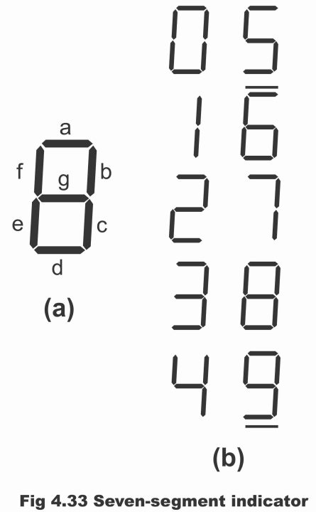
Seven segment display is an electronic component, which contains seven LEDs, which are configured together in such a manner that the decimal digit 8 is composed of them. Thus, due to the application of seven LEDs which are in the form of segments, this component is known as seven segment display. This seven-segment display or electronic component is used to display or demonstrate decimal numbers from 0 – 9 as shown via figure 4.33. LED is used in electronic calculators, clocks, measurement instruments, and scientific equipment in order to display numeric digits from 0 – 9 apart from demonstrating certain English capital letters. As this whole display relies on seven LEDs, or it becomes conceivable by means of seven LEDs, therefore it is known as a seven–segment display.
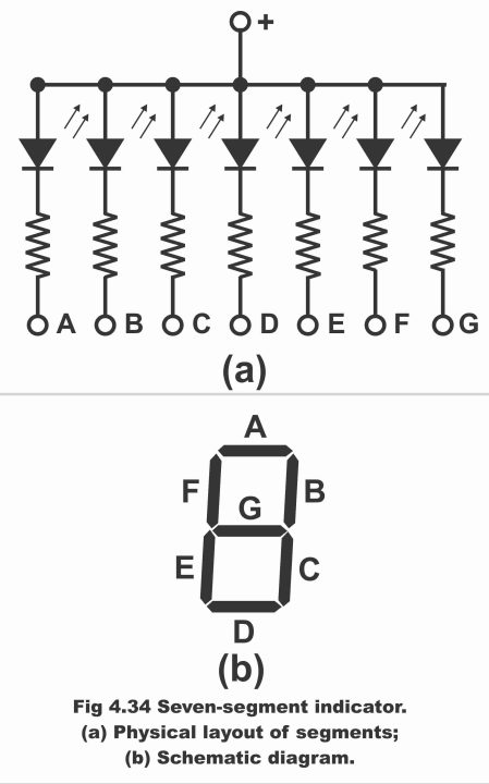
In figure 4.34 (a), a seven-segment indicator has been exemplified, which consists of seven rectangular–shaped light emitting diodes (LEDs) from A to G. As every LED is a segment of the character being displayed, therefore it is known as a segment. In figure (b), the circuit of a seven–segment display has been typified. An external resistor has been mounted along every LED series on the circuit, the function of which is to confine currents within a safe level. By means of grounding one or more than one resistor, we can form any digit from 0 – 9. For example, if A, B, and C are grounded, we get seven (7). And if A, B, C, D, and G are grounded, we get 3. Moreover, in case all segments are radiated, apart from 8 and mid-segment G, zero or digit 0 is obtained (remember that by means of grounding a resistor, its circuit gets accomplished and LED mounted on series of the grounded resistor, irradiates or illuminates. And LEDs connected with un-grounded resistors, do not illuminate). A seven–segment display can exhibit decimal numbers 0 -9, English capital letters A, C, E, and F, and two small English letters b and d. As such any decimal digit can be formatted by means of forward biasing any selected combination of segments.
Figure 4.34 – seven segment indicator (a). the physical layout of segments (b). schematic diagram
Types of Seven–Segment Display
Seven–segment display is of the following two types.
1. common anode type
2. common cathode type
Common Cathode Type
In this type of display, anodes of all LEDs present in the display are interconnected or shorted, as is clear from figure 4.35 (a). The LED which is being desired to be radiated must always be connected to the ground, so that circuit could be completed.
Moreover, in the common anode type, a current limiting resistor is also mounted between every LED and the ground, the size of which depends on the value of the current passing through the LED. In the common anode type, cathodes of seven LEDs existing on the seven–segment LEDs are grounded through different methods for forming various digits from 0 through 9. For example, we want to display the digit 0 (zero). In order to irradiate zero (0), we have to keep “g” on logic 1 whereas all other segments on logic zero. The truth table of 0 – 9 digits of common anode type display has been shown in the figure 4.36.
Figure 4.35 – (a). common – anode type (b). common – cathode type
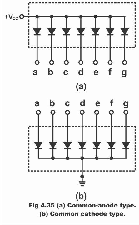
Figure 4.36 – Seven segments common anode type Display Truth Table
| a | b | C | d | e | f | g | Digits | D | C | B | A |
| 0 | 0 | 0 | 0 | 0 | 0 | 1 | 0 | 0 | 0 | 0 | 0 |
| 1 | 0 | 0 | 1 | 1 | 1 | 1 | 1 | 0 | 0 | 0 | 1 |
| 0 | 0 | 1 | 0 | 0 | 0 | 1 | 2 | 0 | 0 | 1 | 0 |
| 0 | 0 | 0 | 0 | 1 | 1 | 0 | 3 | 0 | 0 | 1 | 1 |
| 1 | 0 | 0 | 1 | 1 | 0 | 0 | 4 | 0 | 1 | 0 | 0 |
| 0 | 1 | 0 | 0 | 1 | 0 | 0 | 5 | 0 | 1 | 0 | 1 |
| 0 | 1 | 0 | 0 | 0 | 0 | 0 | 6 | 0 | 1 | 1 | 0 |
| 0 | 0 | 0 | 1 | 1 | 1 | 1 | 7 | 0 | 1 | 1 | 1 |
| 0 | 0 | 0 | 0 | 0 | 0 | 0 | 8 | 1 | 0 | 0 | 0 |
| 0 | 0 | 0 | 0 | 1 | 0 | 0 | 9 | 1 | 0 | 0 | 1 |
Common Cathode
In a common cathode type seven-segment indicator, all LEDs cathodes are connected together as can be seen via figure 4.35 (b). Further, a current limiting resistor is also used between every LED and +VCC in the common cathode type. In such a situation, the desired LED is connected to +5V in order to accomplish the circuit. Thus, by means of connecting inputs a to g with VCC, all digits from 0- 9 can be displayed. Suppose we want to display digit 3, in such a situation, a, b, c, d, and g LEDs will be radiated, whereas the remaining LEDs will be OFF. As such, illuminated LEDs will form digit 3. In figure 4.37, the truth table of entire digits of a common–cathode type display has been shown, in which 1 means LEDs’ illuminated or ON status where 0 means LED’s OFF state.
Figure 4.37 – seven segment common cathode type display truth table
| a | b | C | d | e | f | g | Digits | D | C | B | A |
| 1 | 1 | 1 | 1 | 1 | 1 | 0 | 0 | 0 | 0 | 0 | 0 |
| 0 | 1 | 1 | 0 | 0 | 0 | 0 | 1 | 0 | 0 | 0 | 1 |
| 1 | 1 | 0 | 1 | 1 | 1 | 0 | 2 | 0 | 0 | 1 | 0 |
| 1 | 1 | 1 | 1 | 0 | 0 | 1 | 3 | 0 | 0 | 1 | 1 |
| 0 | 1 | 1 | 0 | 0 | 1 | 1 | 4 | 0 | 1 | 0 | 0 |
| 1 | 0 | 1 | 1 | 0 | 1 | 1 | 5 | 0 | 1 | 0 | 1 |
| 1 | 0 | 1 | 1 | 1 | 1 | 1 | 6 | 0 | 1 | 1 | 0 |
| 1 | 1 | 1 | 0 | 0 | 0 | 0 | 7 | 0 | 1 | 1 | 1 |
| 1 | 1 | 1 | 1 | 1 | 1 | 1 | 8 | 1 | 0 | 0 | 0 |
| 1 | 1 | 1 | 1 | 0 | 1 | 1 | 9 | 1 | 0 | 0 | 1 |
BCD to Seven-Segment Decoder
A BCD to the seven-segment decoder is a combinational logic circuit, which converts input given on BCD into an appropriate code and is used for the selection of segments in a display indicator (which is used for displaying decimal digits in a common or familiar form). In other words, such a combinational logic circuit, which when applied with a standard 8421 or BCD code input, produces a specific 7 – bit output code due to the application of this input, which is then used to drive a 7 – segment display (which reflects decimal numbers), is called BCD to Seven Segment Decoder or drive. Thus, a BCD to seven–segment decoder accepts only BCD codes on its inputs and applies its output to energize seven-segment display devices, which produces decimal read–out. However, seven segment readout is such an electronic component, which takes seven outputs (i.e. a, b, c, d, e, f, g) from the decoder and performs its function to display decimal numbers from 0 – 9 and sometimes specific type of letters (i.e. A, C, E, F, b and d). For this purpose, two or more than two segments of seven segments (which contain seven LEDs) that have been configured properly (i.e. fitted in the form of digit 8) on a display, are irradiated (i.e. seven outputs of the decoder i.e. a to g, select corresponding segments and illuminate it). As such, illuminated segments display various digits (0 – 9) and different letters. Apart from LEDs, these segments can also be manufactured from fluorescent tubes, gas discharge tube or liquid crystal display. In figure 4.33 (a) seven segment display format and in figure (b) digits formed from 0 -9 through seven segments have been shown. Remember that this combinational circuit (i.e. decoder) can normally be found in the type of following numbers in MSC form.
7446 … common anode BCD to seven-segment decoder/drive
7447 … common anode BCD to seven-segment decoder/drive
7448 … common cathode BCD to seven-segment decoder/drive
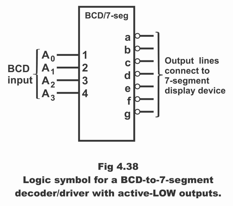
In figure 4.34, the logic symbol of a BCD to seven-segment decoder/drive has been shown along with its active low output. In the figure, 4 BCD inputs can be seen, which the decoder converts into 7 outputs (a to g).
These outputs of the decoder are inputs for the seven-segment display device. Outputs of seven segment decoder (a to g) are connected to display inputs (a to g). It must be indoctrinated here that if you are using a common anode decoder (i.e. 7446 or 7447), it is necessary to use a common anode display along it and if you are using a common cathode decoder (7448), it is essential to always use a common cathode display with it.
Figure 4.38 – a logic symbol for a BCD – to seven-segment decoder/driver with active low inputs
In figure 4.39, a 7446 decoder or driver has been illustrated. This seven-segment decoder is an IC decoder that is applied to drive a seven-segment indicator, as can be seen in the figure. This decoder has four inputs (6, 2, 1, 7) which represent BCD inputs ABCD and has 7 output pins (i.e. 14, 15, 9, 10, 11, 12, 13) which are connected along a seven-segment indicator (a to g). Pin number 16 has been connected to VCC while pin number is ground. According to the figure, this 7446 IC decoder drives a function anode indicator. The logic circuits inside 7416 convert BCD input to the required output.
Figure 4.39 – 7446 decoder – driver
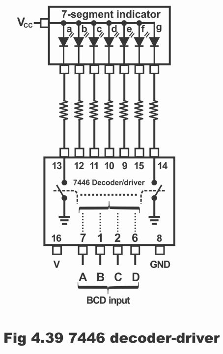
For example, if the value of BCD input is 0111, the inner logic circuit of 7446 (which has been demonstrated here) will conduct or irradiate a, b and c LEDs, whereas rest of the LEDs do not illuminate. As a consequence, digit 7 will appear on seven- segment indicator.
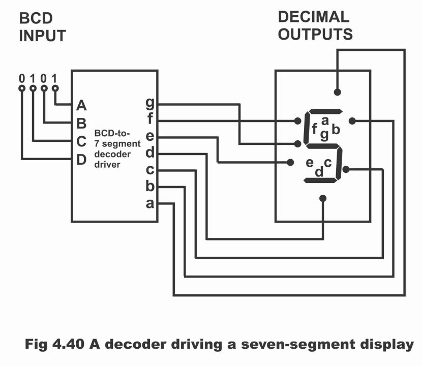
When value of the BCD input is 0101, the decoder radiates all segments (i.e. a, f, g, e, d) of the seven–segment indicator except b and c, as a result digit 5 will be displayed on the seven–segment display. This has been exemplified vide figure 4.40.
Figure 4.40 – a decoder driving a seven–segment display
In figure 4.41, logic symbol of a distinct 7447 TTL (or 741N47) BCD to seven–segment decoder (which drives a seven–segment display by means of decoding a BCD input) has been shown. This MSI device decodes BCD inputs and displays it in the form of a seven–segment display. Apart from decoding and segment drive or display features, 7447 also contains the following merits, as has been elucidated vide logic symbols.
(i). LT Lamp Test
(ii). RPI Ripple Blanking Input
(iii). BI/ RBO Blanking Input/ Ripple Blanking Output
As soon as LT, RBI, and BI/RBO start working, all outputs (a to g) get active low as has been illustrated via bubbles above the logic symbols. These outputs can directly operate a common anode seven–segment display. Remember that the BCD number which is required to be decoded, is applied on inputs A, B, C and D. In figure 4.42, full function of a 7447 decoder/driver IC has been elaborated with the help of a truth table.
Figure 4.41 – the 7447 BCD – to – 7 – segment decoder/driver
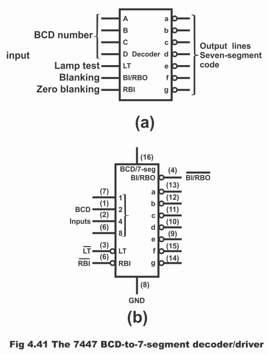
Figure 4.42 – Truth Table for 7447 A Decoder
| INPUTS | OUTPUTS | |||||||||||
| Decimal or function | LT | RBI |
D C B A |
BI/ BRO |
a |
b |
c |
d |
e |
F |
g |
Note |
| 0 | H | H | L L L L | H | ON | ON | ON | ON | ON | ON | OFF | |
| 1 | H | X | L L L H | H | OFF | ON | ON | OFF | OFF | OFF | OFF | |
| 2 | H | X | L L H L | H | ON | ON | OFF | ON | ON | OFF | ON | |
| 3 | H | X | L H L L | H | ON | ON | ON | ON | OFF | OFF | ON | |
| 4 | H | X | L H L L | H | OFF | ON | ON | OFF | OFF | ON | ON | |
| 5 | H | X | L H L H | H | ON | OFF | ON | ON | OFF | ON | ON | |
| 6 | H | X | L H H L | H | OFF | OFF | ON | ON | ON | ON | ON | |
| 7 | H | X | L H H H | H | ON | ON | ON | OFF | OFF | OFF | OFF | |
| 8 | H | X | H L L L | H | ON | ON | ON | ON | ON | ON | ON | 1 |
| 9 | H | X | H L L H | H | ON | ON | ON | OFF | OFF | ON | ON | |
| 10 | H | X | H L H L | H | OFF | OFF | OFF | ON | ON | OFF | ON | |
| 11 | H | X | H L H H | H | OFF | OFF | ON | ON | OFF | OFF | ON | |
| 12 | H | X | H H L L | H | OFF | ON | OFF | OFF | OFF | ON | ON | |
| 13 | H | X | H H L H | H | ON | OFF | OFF | ON | OFF | ON | ON | |
| 14 | H | X | H H H L | H | OFF | OFF | OFF | ON | ON | ON | ON | |
| 15 | H | X | H H H H | H | OFF | OFF | OFF | OFF | OFF | OFF | OFF | |
| BI
RBI LT |
X
H L |
X
L X |
X X X X
L L L L X X X X |
L
L H |
OFF
OFF ON |
OFF
OFF ON |
OFF
OFF ON |
OFF
OFF ON |
OFF
OFF ON |
OFF
OFF ON |
OFF
OFF ON |
2
3 4 |
H = High Level L= Low Level X= Irrelevant
Notes;
1. The blanking input (BI) must be open or held at a HIGH logic level when output functions 0 through 15 are desired. The ripple–blanking input (RBI) must be open or high if blanking of a decimal zero is not desired.
2. When a low logic level is applied directly to the blanking input (BI), all segment outputs are OFF regardless of the level of any other input.
3. When ripple–blanking input (RBI) and inputs A, B, C, and D are at low level with the lamp test (LT) input HIGH, all segment outputs go OFF and the ripple–blanking output (RBO) goes to a LOW level (response condition)
4. When the blanking input/ ripple output (BI/ RBO) is open or held HIGH and a LOW is applied to the lamp test (LT) input, all segment – outputs are ON.
When LT input goes LOW, and BI/RBO goes HIGH, all seven segments existing on the display, go ON or activate. Or all output (a through g) go ON. Look at final line of the truth table. In order to know whether any of the segments is burnt–out, a lamp test is carried out.
When the blanking input is low, all segments go OFF. This characteristic is used when numerous 7 – segment displays are applied in a group form in order to read out numbers with more than one digits. As a result of this feature, all zeroes preceding the actual number are depleted or they do not irradiate at all. This feature is called zero suppression. For example, if all zeroes on 18 digits display preceding to the actual number are not eliminated or blanked out, the number 1676 will be displayed as 00001676. When all zeroes preceding to 1676 are removed or blanked out (blank means that no LED present on the display goes illuminated), then this number is visible only in its actual form 1676, and rest of the four zeroes do not illuminate at all.
This point can be elaborated further with the help of an example. For example, if already existing zeroes or not abolished or blanked out on 6 digits display, numbers 4 and 6 will display like this 006.400. The process of blanking out or eliminating zeroes in the beginning of this number is called leading zero suppression and doing away with zeroes at the end of number, is called trailing zero suppression. It has to be kept in mind that only unnecessary zeros are blanked out. Through zero suppression function, 030.080 will be displayed as 30.80 (here zeroes, which are necessary, have not been omitted whereas unnecessary zeroes have been blanked)
In 7447 the zero-suppression process is performed by means of using RBI and BI / RBO functions. Both BI and RBO deal with one pin which means that BI/RBO pin may be used as an input or output. When it is used as BI, then all segment outputs are high (non–active) when BI is low, as a result, all other inputs become invalid. Remember that BI function has nothing to do with zero suppression feature of the device.
If zero code (0000) exists on BCD inputs and if its RBI is low, all segments outputs of the decoder go non–active (high), as a result of which the display goes blank and RBO also becomes low. In short, the following aspects must be kept in mind regarding additional features of this type of decoder.
(1). When output functions are required from 0 through 15, blanking input (BI) must be open or on high logic level. If blanking of decimal zero is not desired, ripple blanking input (RBI) must be open or high.
(2). When BI has applied a low logic level directly, then regardless of logic level of any other input, segment outputs are OFF.
(3). When RBI and ABCD inputs are on low level, whereas lamp test (LT) input is high, then all segment outputs go OFF, as has been demonstrated by a truth table. Remember that all outputs of 7447A IC are normally high. When they are activated, they tend to go low. That’s the reason they are known as active low outputs. Further, invalid BCD inputs (10, 11, 12, 13, 14 and 15) also produce output on 7447A decoder.
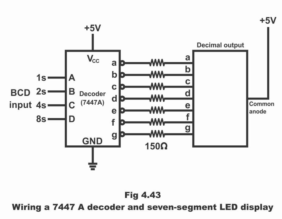
7447- decoder is connected with a seven-segment LED display via seven limiting resistors, as can be seen in figure 4.43. The operational mechanism of this device is as follows:
Suppose that BCD input value applied on 7447A decoder is 0001 (i.e. LLLH). As a consequence of this input, c and b outputs of the decoder become low, due to which c and b segments on the seven–segment display gets irradiated or illumined and decimal 1 appears on the display screen. In this figure, LT and two blanking inputs (BIs) have not been illustrated, which under such a situation are assumed to have been deactivated on the circuit (i.e. they do not operate) due to high floating or they do not affect this circuit in any way. In a perfect design, these floating inputs are connected to +5V, so that they may always remain high.
Figure 4.43 – wiring a 7447 decoder and seven–segment LED display
When value of BCD input is 0011(i.e. LLHH), all segment outputs except e and f turn ON or they tend to radiate. As a result, the decimal digit 3 appears on LED display as can be seen through line No. 4 of the given table.
When the value of BCD input is 0110 (i.e. LHHL) a and b segments turn blank (i.e. they do not radiate) whereas all other outputs except a and b, become ON or they get irradiated or illumined. As a result, digit 6 displays on decimal output.
Similarly, when the value of BCD input is 1001 (i.e. HLLH) then all segments (a, b, c, f, g) except e and d irradiate, and resultantly digit 9 appears on the decimal output, which can be seen in line No. 10 of the truth table.
Previous Topic: Decoder logic circuit diagram and operation
Next Topic: BCD Encoder circuit diagram and truth table in digital electronics
For electronics and programming-related projects visit my YouTube channel.


